As a smart hydration specialist, I spend a lot of time tracing “mystery” water issues in homes that have whole‑house filtration, under‑sink drinking systems, and well or booster pumps. Very often, the real troublemaker is not a filter cartridge or a fancy controller, but a simple pressure switch that is acting far more often than it should.
When a pressure switch clicks on and off constantly, or trips and shuts you down at the worst possible time, you face an important question: is this a settings problem you can safely correct, or is it time to replace the switch altogether?
In this guide, I will walk you through how pressure switches work, what “frequent actions” really mean, and how to make a science‑based decision to adjust, relocate, or replace the switch in a way that protects both your water equipment and your household’s hydration comfort. The discussion is grounded in technical guidance from manufacturers and HVAC experts such as BCST Group, SUCO ESI North America, Argent Heating & Cooling, Cycle Stop Valves, Nason, Fieldpiece, and others, with examples adapted for home water systems.
Why Pressure Switches Matter in Home Hydration Systems
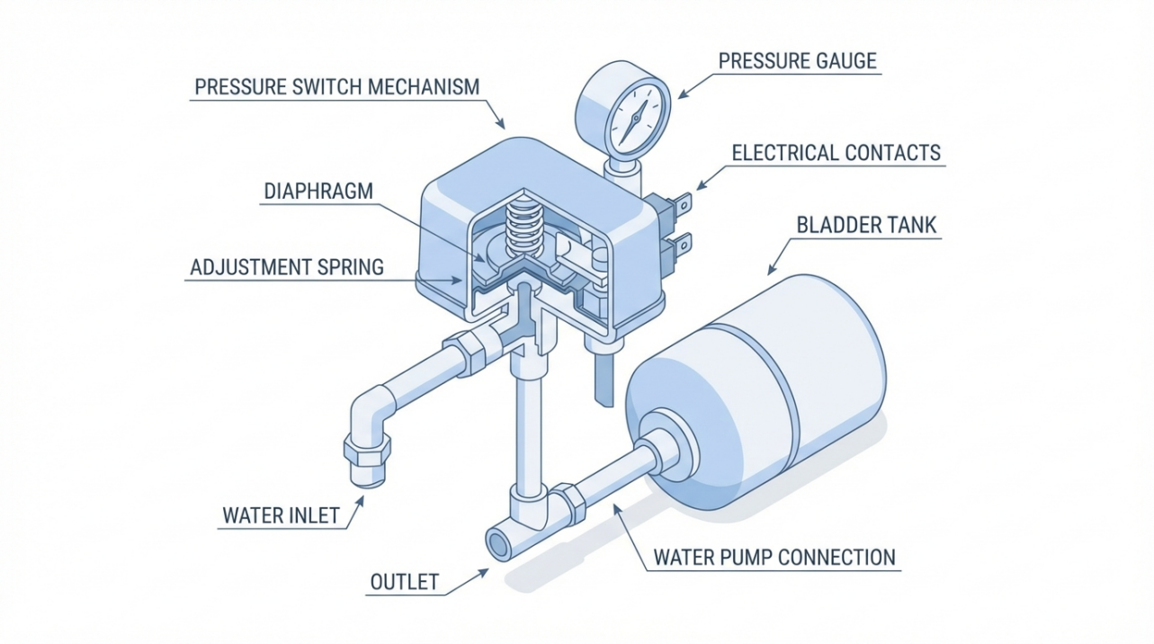
Pressure switches are electromechanical control devices that sense changes in pressure and turn an electrical circuit on or off. BCST Group describes them as compact devices where a diaphragm or piston responds to system pressure, compresses a calibrated spring, and moves contacts to open or close a circuit. In everyday terms, they are the traffic lights for your pump or compressor.
In a home hydration system, a pressure switch might:
- Start and stop a well pump that supplies a whole‑house filtration system.
- Control a booster pump feeding a multi‑stage under‑sink system.
- Protect a compressor on a carbonated water or chilled water unit.
- Monitor pressure across filters or storage tanks in more advanced installations.
Two pressures define how a standard mechanical switch behaves. The cut‑in pressure is the lower point where the switch closes the circuit and turns equipment on. The cut‑out pressure is the upper point where it opens the circuit and turns equipment off. The difference between them is called the differential. BCST Group gives a classic example: if cut‑in is 40 psi and cut‑out is 60 psi, the differential is 20 psi.
Argent Heating & Cooling notes that in compressed‑air systems, these switches are not just for convenience but also for safety, preventing over‑pressurization that could damage equipment or create hazards. The same principle applies to water systems feeding your home filtration: a correctly functioning switch helps keep pressure within the safe, usable range that your housings, tubing, and fittings are designed to handle.
Pressure switches are also available in normally open and normally closed contact configurations. BCST Group explains that in a normally open design the contacts stay open at normal pressure and close when pressure moves beyond the acceptable range, while normally closed switches do the opposite. Many field‑adjustable switches include at least one of each contact type so they can integrate into different control schemes.
For homeowners, the key takeaway is that this small device is managing when pumps run, how often they start, and whether the system safely shuts down when pressure is too low or too high. When it starts acting more frequently than usual, your water comfort and equipment lifespan are both at stake.

Understanding “Frequent Actions”: What Your Switch Is Telling You
“Frequent actions” can show up in several ways. Homeowners describe it as rapid clicking from the switch box, pumps that start and stop every few seconds, or a system that seems to shut down every time someone takes a shower. From a technical standpoint, experts such as Argent Heating & Cooling and BCST Group refer to this as short cycling or nuisance tripping.
Short cycling occurs when the pressure switch cuts in and cuts out so often that the pump barely has time to run before being shut off again. Argent Heating & Cooling points out that incorrectly set cut‑in and cut‑out pressures are a common cause, leading to short cycling, failure to start, or even over‑pressurization. SUCO ESI North America emphasizes that setting the pressure differential too small can also cause rapid cycling because the system pressure crosses the narrow band repeatedly.
Another pattern of frequent action is repeated safety trips. High‑pressure switches in HVAC systems, described by Momentum AC and Miracle Refrigeration, open the circuit and stop compressors when pressure rises above a preset limit. They note that issues such as overcharging, blocked coils, restricted airflow, or other system faults can cause repeated high‑pressure trips. In water and filtration systems, an analogous situation is a pressure switch or differential pressure switch responding repeatedly to restrictions or blockages rather than to a bad switch.
Tameson notes that differential pressure switches are commonly installed across filters to watch the pressure difference between upstream and downstream. As the filter clogs, the differential increases, eventually reaching the switch setpoint, which can trigger an alarm or shutdown. In a home hydration context, if a smart controller or switch is monitoring pressure across a dense carbon block or membrane prefilter, frequent trips may point to a clogged cartridge rather than a defective switch.
Furnace and boiler experts add another perspective. CFM Distributors explains that in modern furnaces, pressure switch fault codes often do not mean the switch itself is bad. Their technical letter stresses that issues such as blocked venting, condensate problems, or corroded ports can prevent proper pressure from reaching the switch even when system pressure is otherwise correct. Fieldpiece likewise highlights that obstructions, blocked flues, and clogged pressure tubing can cause erratic ignition cycling that looks like switch failure but is really a system problem.
Across all these applications, a pattern emerges. When a pressure switch is acting more often than expected, the root cause may be:
- Incorrect settings or differential.
- Poor placement or installation that exposes the switch to hydraulic shock or turbulence.
- System problems such as clogged filters, blocked lines, or venting issues.
- Mechanical wear, contamination, or damage inside the switch.
The challenge is to distinguish which of these you are dealing with before deciding to adjust or replace.

When Adjustment Is the Smarter First Move
In many home water and filtration systems, especially when equipment is relatively new, the first and most cost‑effective step is to evaluate and correct settings and installation rather than buying a new pressure switch immediately.
Signs That Settings, Not Hardware, Are the Likely Culprit
Several clues point toward adjustment as the right starting point.
When cycling issues appear soon after an installation or after adding new components such as additional filters or a new storage tank, settings and configuration are prime suspects. SUCO ESI emphasizes that the first step in adjustment is to determine the desired cut‑in and cut‑out pressures from system requirements instead of turning screws blindly. BCST Group adds that understanding how the range and differential adjustments interact is essential, because changing one can shift both cut‑in and cut‑out.
BCST Group’s example of a 40 psi cut‑in and 60 psi cut‑out with a 20 psi differential is a useful reference. They note that in standard mechanical switches the larger adjustment nut typically changes the overall range, moving both cut‑in and cut‑out up or down, while a smaller nut controls the differential. If the differential is accidentally set very narrow, pressure will move through that band quickly and create short cycling. SUCO ESI’s guidance that too small a differential causes rapid cycling directly supports this.
For bladder‑tank water systems, BCST Group highlights another key parameter: air pre‑charge. They recommend setting the tank pressure to about 2 psi below the switch’s cut‑in when the tank is empty. In their example, if the cut‑in is 40 psi, the tank pre‑charge should typically be no more than 35 to 38 psi, keeping at least a 2 to 5 psi gap. If pre‑charge is set too close to cut‑in, the switch may trip or chatter instead of transitioning cleanly.
BCST Group also cautions that factory pressure switches are not always individually calibrated. A model labeled 30 to 50 psi might, in practice, operate anywhere from about 28 to 48 psi, and switches can sometimes stick, showing a one to three psi difference from one cycle to the next. A small mismatch between expectation and reality does not necessarily mean the switch is bad; it may simply need adjustment and verification.
When your home water system’s symptoms match these patterns—recent changes, very tight pressure band, tank pre‑charge set equal to cut‑in, or behavior that is off by a few psi—adjustment is often the logical first intervention.
A Practical, Safe Adjustment Process
Technical sources all converge on a few safety fundamentals before touching a pressure switch. BCST Group, SUCO ESI North America, and Nason all stress disconnecting power to the switch, following lockout and tagout procedures where applicable, and depressurizing the system if necessary. This is essential not only to protect you from electrical shock and sudden water releases, but also to prevent damage to the switch as you adjust it.
The process for a typical well pump or booster pump switch serving a filtration system often looks like this, in principle.
Begin by documenting where you are. BCST Group suggests measuring and recording the distance from the exposed thread at the top of the adjustment stud to the top of the nut before you change anything. That simple measurement, in fractions of an inch, gives you a way to return to original settings if needed.

Next, set your target pressures. SUCO ESI recommends determining your desired cut‑in and cut‑out pressures from equipment specifications or design requirements. For many residential systems, a band somewhat like the 40 psi to 60 psi example from BCST Group is common, but the exact values should reflect what your filters, fixtures, and occupants need.
Then adjust the range and differential carefully. On standard mechanical switches, BCST Group reports that the larger nut usually adjusts the range or cut‑in, while the smaller nut affects the differential. They recommend limiting each adjustment to about three turns at a time to avoid thread damage and to maintain fine control. SUCO ESI notes that turning the appropriate screw clockwise generally raises the set pressure and turning it counterclockwise lowers it, while you watch the system pressure on a gauge.
BCST Group explains that when you adjust cut‑in by a certain amount on many switches, cut‑out will move by the same amount. For example, if you increase cut‑in by 10 psi, cut‑out will also increase by roughly 10 psi, preserving differential. That means you can shift the entire operating window up or down while keeping the same band width.
Once the adjustments are made, monitoring is essential. BCST Group lays out a water‑system‑friendly verification method. Drain water from the system using a drain or faucet until pressure falls below the intended cut‑in so that the pump starts. Then close the faucet and observe the pressure gauge as the pump builds pressure and fills the tank, noting where the pump shuts off at cut‑out. Repeat this process over several cycles, making small corrections until the system consistently starts and stops at the desired pressures.
For those who need tighter tolerances—for example, in a smart hydration system feeding sensitive devices—advanced tools can help. Fluke describes calibrating a pressure switch using an automatic pressure calibrator that ramps pressure up and down, detects exactly where the contacts close and open, and calculates dead band. In their example, a switch with a nominal 10 psi setpoint and a tolerance of plus or minus 2 psi measured a setpoint of 10.5 psi and a reset of about 9.5 psi, yielding a one psi dead band, which passed the specified tolerance. While homeowners typically will not own such a calibrator, this illustrates how professionals verify that a switch is performing within specification rather than guessing.
Placement and Installation Tweaks to Calm a “Bouncing” Switch
Even a perfectly adjusted pressure switch can misbehave if it is installed in the wrong place. Cycle Stop Valves, which specializes in pump and tank systems, has documented how incorrect pressure switch placement leads to “bouncing” or “telegraphing” in systems with bladder tanks.
They consider it a mistake to tap the pressure switch anywhere along the main line where water flow is turbulent. In that position, the switch sees every surge, hydraulic shock, and velocity change before the expansion volume in the tank has time to respond. The result is rapid on‑off cycling or “pump bumping” instead of smooth drawdown.
Their recommended best practice is to install a small line, not larger than the tank’s inlet and at least about a foot long, from the main line to the bladder tank and to mount the pressure switch on a tee at the end of this small line, as close to the tank as possible. The chosen tank should be at the end of a line where no flow passes through, so tank water volume changes before the switch senses pressure changes. In multi‑tank setups, they suggest selecting one tank as the reference point and following this placement rule to stabilize the switch and avoid the need for snubbers.
Cycle Stop Valves also warns about placing the switch on the air side of a bladder tank. In non‑bladder hydropneumatic tanks, mounting the switch on the air space historically worked well and isolated it from hydraulic shock. With bladder tanks, however, they note that air molecules can migrate through the pressure switch diaphragm over time, allowing air to escape from the tank and eventually leaving it waterlogged. This leads to poor performance and potential pump failure. For bladder tanks, they emphasize that the pressure switch must be installed on the water side near the tank, not on the air side.
Installation quality more broadly matters as well. SUCO ESI’s guidance on pressure switch installation in industrial and HVAC settings notes that a high percentage of early failures—on the order of sixty to eighty percent—are traced to installation errors rather than defective devices. They highlight problems such as mis‑sized ranges, poor environmental protection, and improper mounting. For a smart home hydration setup, that translates to selecting a switch whose pressure range is appropriate for your operating pressures, mounting it in a vertical orientation where it can drain, and protecting it from vibration, moisture, and temperature extremes as recommended by the manufacturer.
When you combine correct settings, proper pre‑charge, and thoughtful placement, many cases of frequent switching calm down without replacing the device.
When Replacement Is Safer and More Reliable
There are clear situations where continuing to adjust an older or damaged pressure switch is false economy. At that point, replacement—often with a better‑matched or more modern design—protects both your hydration system and your peace of mind.
Mechanical Wear, Contamination, and Drift
Mechanical pressure switches rely on moving parts: diaphragms or pistons, springs, and electrical contacts. Argent Heating & Cooling notes that wear of the diaphragm or piston can lead to inaccurate pressure sensing and erratic behavior. They also point to sticking or dirty electrical contacts as a frequent cause of malfunction, and they recommend regular inspection and cleaning where appropriate.
CFM Distributors’ furnace pressure switch guidance adds an important clue. They explain that pressure switches often include a small bleed hole to keep the diaphragm area dry. If water is found inside the switch, particularly in applications with condensate, it usually indicates a problem with that bleed port, and the switch should be replaced rather than repaired. While their examples focus on flue gas and condensate, the same logic applies if a water system pressure switch is visibly waterlogged or corroded internally.
Nason’s guide to field‑adjustable pressure switches stresses that if a switch does not respond to adjustments, or shows inconsistent readings even after careful calibration, issues such as dirt, debris, corrosion, or worn diaphragms may be at play. They advise checking pressure readings with a reliable gauge and assessing environmental factors such as temperature and humidity. When a switch frequently fails or behaves erratically despite proper setup and environment, replacement becomes the sensible choice.
Another factor is age. SUCO ESI’s discussion of mechanical versus electronic pressure switches for HVAC systems indicates that mechanical designs often have service lives in the range of ten to fifteen years under typical conditions. In demanding climates, high vibration, or corrosive environments, life can be shorter. For a well pump switch or booster pump switch that has been in service for a decade or more, recurring issues and frequent adjustment needs are warning signs that it has reached the end of its reliable life.
Safety‑Critical Roles: Err on the Side of New Hardware
Pressure switches sometimes serve as safety interlocks rather than everyday control devices. Fieldpiece describes furnace pressure switches whose primary purpose is to prevent harmful combustion gases from entering living spaces and to reduce the risk of fires or explosions. They are designed to open the circuit and shut down the furnace when draft or venting conditions are not within manufacturer specifications.
CFM Distributors explains that modern furnace control boards monitor these switches continuously, interrupting heat on any unexpected opening, and that diagnostic codes help distinguish between wiring issues, inducer problems, vent restrictions, and true pressure switch failures. However, they also make clear that if a switch fails to close or opens repeatedly under correct pressure conditions, it should be replaced.
In a home hydration context, similar safety roles can appear in integrated systems where water appliances share space with combustion appliances or where pressure switches are tied into more complex control or alarm circuits. Whenever a pressure switch is part of a safety chain, and it is suspected to be unreliable, replacement with a properly rated switch—often the original equipment manufacturer part—should be prioritized over repeated adjustments.
Fieldpiece also recommends that technicians keep universal pressure switches available for temporary restoration of operation but communicate clearly to homeowners that an original equipment switch may provide a more exact match and should be installed when possible. That mindset, favoring precise fit in safety‑critical roles, is good practice for any homeowner relying on safe, continuous hydration and heating.
Choosing Between Mechanical and Electronic Replacement Options
When replacement is on the table, you have an opportunity not just to swap like for like, but to consider whether a different switch technology fits your hydration system better.
SUCO ESI’s guidance for AC and HVAC systems in demanding climates compares mechanical and electronic pressure switches in detail. Mechanical switches use springs and diaphragms, do not require external power to sense pressure, and often cost significantly less than electronic options. SUCO ESI notes that they can offer a service life in the ten to fifteen year range, cover wide operating ranges, and are well‑suited to basic high and low cut‑out and safety functions.
Electronic pressure switches, by contrast, use advanced sensors and electronics to provide high accuracy and programmable behavior. SUCO ESI cites accuracies around plus or minus a quarter percent for certain electronic devices, compared to plus or minus two to three percent typical for mechanical switches. These electronic units can offer multiple programmable setpoints, digital or analog outputs, and integration with building automation or smart monitoring systems.
For a smart home hydration system that already includes connectivity, data logging, or remote alerts, an electronic pressure switch or transmitter can be a strategic upgrade when replacement is needed. Nason discusses solid‑state switches that use electronic sensors for higher precision and reliability, and their guidance on adjustment, fine‑tuning, and troubleshooting applies well to these devices.
That said, for a simple well pump feeding a whole‑house filter, a correctly selected and installed mechanical pressure switch remains a proven, robust choice. SUCO ESI emphasizes that proper range selection—keeping normal operating pressure in the middle sixty to seventy percent of the switch range—is more important than technology type for longevity and reliability.
Decision Guide: Adjust, Improve, or Replace?
Based on the combined guidance from BCST Group, SUCO ESI, Cycle Stop Valves, Argent Heating & Cooling, Nason, Fieldpiece, CFM Distributors, Tameson, and others, you can think of the adjust‑versus‑replace decision in a structured way.
Here is a concise comparison to anchor your thinking.
Situation in your system |
Best first move |
New or recently modified system with rapid cycling, tight pressure band, no visible damage |
Verify cut‑in, cut‑out, and differential against design; adjust settings and tank pre‑charge; confirm installation and placement near the tank. |
Frequent trips associated with filter changes or known restrictions |
Inspect for clogged filters or blocked lines; use differential pressure or system pressure readings to address the restriction before altering switch settings. |
Switch mounted on turbulent main line far from bladder tank |
Relocate the switch to a small line or tee as close to the tank as practical, following Cycle Stop Valves’ placement guidance. |
Older switch showing corrosion, moisture inside, or inconsistent behavior despite tuning |
Replace the switch with a properly rated unit; for smart systems, consider upgrading to a solid‑state or electronic device. |
Switch in a safety‑critical role (combustion venting, over‑pressure protection) with doubtful reliability |
Engage a qualified professional and favor replacement with an original equipment or manufacturer‑approved switch. |
This table is not a substitute for manufacturer instructions, but it reflects patterns seen repeatedly in technical literature and field experience across water, air, and HVAC systems.
Real‑World Example: A Well Pump Feeding Whole‑Home Filtration
To make the decision process concrete, consider a common scenario that echoes BCST Group and Cycle Stop Valves’ guidance.
A homeowner has a well pump and bladder tank that supply water to the whole house, including a multi‑stage sediment and carbon filtration system. The pressure switch is nominally set to start the pump at 40 psi and stop at 60 psi. Recently, they have noticed the pump clicking on and off frequently, even during modest water use at a single faucet.
An inspection shows that the tank air pre‑charge, measured with the tank empty, is set at 40 psi—the same as the switch’s cut‑in. BCST Group explains that in bladder‑tank systems the pre‑charge should be set to about 2 psi below cut‑in, and that if pre‑charge is too close to cut‑in, the pressure switch may trip repeatedly. In this case, the adjustment target would be in the 35 to 38 psi range.
The pressure switch, meanwhile, is mounted on a tapping in the main line several feet upstream of the tank. Cycle Stop Valves warns that locating the switch on the main line allows line turbulence and hydraulic shock to “bounce” the switch, causing rapid cycling instead of allowing the tank volume to buffer pressure changes.
The corrective strategy starts with adjustment and placement, not replacement. Power is disconnected and lockout is observed. The pre‑charge is lowered slightly to bring it a couple of psi below the intended cut‑in, with the tank empty. The pressure switch is relocated to a small line and tee directly at the tank inlet, in line with Cycle Stop Valves’ best practice.
Then, following BCST Group’s advice, the range and differential nuts are adjusted in small increments to align actual cut‑in and cut‑out with the desired 40 psi and 60 psi. The system is cycled multiple times by draining and refilling, verifying that the pump starts and stops at consistent pressures and that the new placement has eliminated bouncing.
After these steps, the pump runs for longer, smoother intervals, the pressure at taps is more stable, and the switch is no longer clicking incessantly. No replacement was needed; disciplined adjustment and relocation resolved the frequent actions.
In a different scenario, imagine a similar system where the switch is more than a decade old, the contacts are visibly corroded, and even after proper adjustment and placement the switch closes intermittently at random pressures. Nason’s troubleshooting framework, combined with SUCO ESI’s service life expectations for mechanical switches, would support replacement. At that point, the homeowner might choose either a new mechanical switch with the correct range or, for a more integrated smart system, an electronic pressure switch that can feed data to a controller or app.
Working with Professionals and Staying Within Your Comfort Zone
Many homeowners can safely verify pressure settings and tank pre‑charge if they are comfortable shutting off power, using a pressure gauge, and following written instructions. SUCO ESI and BCST Group both stress that adjustments should always be carried out with the system de‑energized, with clear understanding of which screw controls which parameter, and with small, incremental changes followed by careful monitoring.
However, several situations call for a qualified professional:
When your pressure switch is tied into a furnace, boiler, or other combustion appliance, Fieldpiece and CFM Distributors both emphasize its role as a safety device. In those cases, testing often requires specialized tools such as digital manometers and an understanding of venting codes and fault diagnostics.
When your hydration system is integrated with more complex HVAC controls, variable speed drives, or building automation, the logic used to interpret pressure switch signals can be intricate. HVAC professionals, as reflected in the technical literature, routinely encounter programs where fan or pump status must be proven before control outputs ramp up. Incorrect adjustment in such systems can create deadlocks where equipment never reaches proper operating speed.
When your system includes refrigerant‑based chillers or heat pumps feeding chilled or sparkling water, guidance from refrigeration experts such as Miracle Refrigeration and Momentum AC underscores that pressure switches on refrigerant circuits must be selected, adjusted, and replaced with close attention to refrigerant pressures, high‑pressure safety limits, and manufacturer ratings.
In all of these cases, partnering with a technician who understands both pressure switch behavior and the specifics of your equipment keeps your home hydration safe and reliable.
Short FAQ
How often should a pressure switch in a home water system be replaced?
There is no single calendar rule, but guidance from SUCO ESI suggests that mechanical pressure switches often deliver service lives on the order of ten to fifteen years when properly selected and installed. If your switch is in that age range and you start seeing inconsistent performance, repeated cycling issues, or visible corrosion despite correct settings and placement, replacement is a reasonable step to discuss with a professional.
Is it safe to adjust my own pressure switch?
Technical references from BCST Group, SUCO ESI, and Nason agree on two points. First, adjustment can be safe for someone who is confident working around electrical equipment and pressurized systems, provided that power is fully disconnected, system pressure is relieved when needed, and manufacturer instructions are followed carefully. Second, changes must be made in small increments, with pressure monitored by a reliable gauge and system operation observed over several cycles. If you are unsure, or if the switch is part of a safety chain for combustion or high‑pressure refrigerant equipment, working with a qualified technician is the safer path.
Can frequent pressure switch trips affect how well my home filtration works?
The technical literature reviewed here focuses mainly on equipment safety and reliability rather than water quality itself. However, sources such as Tameson and Miracle Refrigeration point out that pressure and flow conditions directly affect how filters and heat exchangers perform. In practice, frequent trips and short cycling often translate into unstable flow through filters and membranes. Stabilizing pressure and cycling behavior by correctly adjusting or replacing switches helps your hydration system operate as its designers intended, which supports consistent filtration performance.
Smart hydration is not just about the filter cartridges you choose; it is about how every control component, including humble pressure switches, works together to maintain stable, safe pressure. By reading the signals your switch is sending you, starting with careful adjustment and installation, and knowing when to step up to a replacement, you protect both your equipment and the steady, clean water your home depends on.
References
- https://docs.lib.purdue.edu/cgi/viewcontent.cgi?article=1368&context=ihpbc
- https://people.eecs.berkeley.edu/~culler/cs294-f09/m197content.pdf
- http://web.mit.edu/parmstr/Public/TC75/A11_Ch42_I-P_SI-2015%20DRAFT-ncmt4.pdf
- https://aichat.physics.ucla.edu/index_htm_files/browse/ZnbzRG/Wiring_Diagram_Pressure_Switch.pdf
- https://www.achrnews.com/articles/92875-the-essentials-of-working-with-r-410a
- https://bcstgroup.com/how-to-adjust-the-pressure-switch-correctly/
- https://cyclestopvalves.com/pages/correct-pressure-switch-placement-stops-bouncing-or-telegraphing
- https://www.justanswer.com/hvac/ahk4l-high-pressure-switch-fixed-right.html
- https://sucoesi.com/how-to-adjust-pressure-switch/
- https://tameson.com/pages/differential-pressure-switch

Share:
Understanding Why Your RO System Sometimes Refuses to Operate
Understanding Why Your Pump Starts But Lacks Pressure